Alternator Wiring: A Comprehensive Guide

Automobiles rely on a complex system of components to function efficiently, and one crucial element in this intricate network is the alternator. The alternator is the powerhouse of a vehicle, responsible for converting mechanical energy into electrical power. Understanding the wiring of this essential component is fundamental for maintaining optimal performance in any vehicle. Let’s delve into the intricacies of alternator wiring and its significance.
The Basics of Alternator Wiring
The alternator is connected to the battery and generates electricity through electromagnetic induction. This electrical energy powers the various electrical systems in the vehicle and keeps the battery charged. Understanding the wiring setup of an alternator involves comprehending the primary components and their connections:
- Stator: The stator consists of wire coils that remain stationary within the alternator. As the rotor spins, it induces an alternating current (AC) in the stator windings.
- Rotor: The rotor is the rotating part of the alternator. It generates a magnetic field as it spins within the stator, which induces an electrical current in the stator windings.
- Diodes: Alternators contain diodes that convert the AC produced by the stator into direct current (DC) before sending it to the battery and electrical systems. These diodes are arranged in a configuration known as a rectifier.
- Voltage Regulator: The voltage regulator controls the output of the alternator, ensuring a steady voltage supply to the battery and electrical components. This prevents overcharging of the battery or voltage spikes that could damage the vehicle’s systems.
Understanding the Wiring Connections
The wiring connections of an alternator may vary based on the vehicle’s make, model, and manufacturer. However, they generally follow a standard wiring configuration:
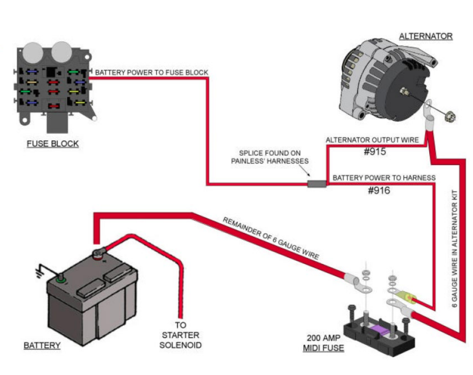
- Battery Connection: The alternator is connected to the battery through a positive wire that allows the electrical energy generated to charge the battery. This connection ensures a continuous power supply to the vehicle’s electrical systems.
- Stator Connection: The stator wires are connected to the rectifier assembly, where the AC voltage generated in the stator windings is converted into DC voltage. These connections are crucial for transforming the alternating current into usable direct current.
- Voltage Regulator Connection: The voltage regulator is often integrated into the alternator or connected separately. It monitors the battery’s state of charge and adjusts the alternator’s output to maintain a consistent voltage level.
- Ground Connection: A secure ground connection is essential for the alternator to function correctly. It completes the circuit and provides a path for electrical current to flow.
Troubleshooting Alternator Wiring Issues
Understanding alternator wiring is vital when diagnosing and fixing potential problems. Issues such as loose connections, damaged wires, faulty diodes, or a malfunctioning voltage regulator can affect the alternator’s performance, leading to electrical system failures or a drained battery.
Common troubleshooting steps include:
- Checking connections for corrosion or looseness.
- Testing the voltage output of the alternator.
- Inspecting the condition of wires and diodes for any signs of damage or wear.
Conclusion
Comprehending the wiring of an alternator is integral for maintaining a vehicle’s electrical system. A properly functioning alternator ensures a steady power supply to keep the battery charged and the various electrical components operating efficiently. Regular inspection, maintenance, and understanding of alternator wiring can prevent potential issues, ensuring a smooth and reliable driving experience.


